
Summary: Even a high-precision tilt sensor delivers poor data if installed incorrectly. Mount the sensor on a rigid, flat, clean surface using solid brackets, avoiding flexible or vibrating substrates. Align the sensor’s measurement axis with the direction of expected movement. Keep the sensor away from EMI sources such as motors, inverters, and high-voltage cables, and shield cables where needed. After installation, perform zero calibration with the structure in its reference (unloaded) state — electronically, if available, rather than fighting for perfect physical alignment. Never zero under load, and never use re-zeroing to mask a loose bracket.
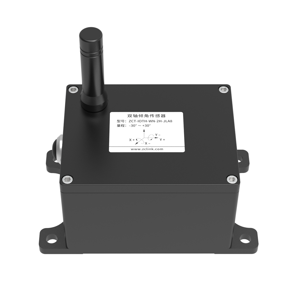
1. Why Installation Determines Data Quality
A tilt sensor’s datasheet accuracy is measured on a laboratory bench. In the field, installation quality often dominates the errors that actually appear in the data. Mounting tolerances, surface irregularities, slight misalignment, and environmental interference can introduce offset errors far larger than the sensor’s intrinsic accuracy.
The good news: most installation errors are avoidable with proper technique. This guide covers the five factors that determine field data quality: mounting surface, axis alignment, electromagnetic interference, thermal stability, and zero calibration.
2. Mounting Surface: Rigid, Flat, and Clean
The mounting surface is the mechanical foundation of your measurement. A loose or flexible mount makes the sensor read its own vibration and movement rather than the structure.
- Use solid metal or reinforced structural mounting points — avoid thin plates that bend under vibration
- Clean the mounting area: remove rust, paint, and debris before installation
- Torque bolts to specification and use thread-locking compound to prevent loosening over time
- Ensure the sensor makes full rigid contact with the surface — no gaps, no soft spacers
- Apply fastening force evenly to avoid deforming the sensor base and introducing offset
A common rule of thumb in installation practice: if the bracket flexes when you push on it, the mounting is not rigid enough.
3. Axis Alignment: The Two Faces, Two Axes Rule
Alignment errors create systematic offsets that no amount of post-processing fully removes. Two alignments matter:
- Mounting face parallel to the measured surface: The sensor’s mounting face must sit flush against the structure’s surface, with no angular gap. An uneven surface introduces a constant tilt error.
- Measurement axis parallel to the expected movement direction: The sensor’s X (or Y) axis must align with the direction of expected tilt. Misalignment produces cross-axis error — part of the movement leaks into the other channel.
For long-term monitoring, consistency matters more than perfect alignment to Earth’s horizon. The goal is that the sensor reports angles relative to a well-defined structural state. This is where electronic zeroing becomes valuable: instead of spending hours with shims and spirit levels to achieve a 0.00 reading, install the sensor securely and command it to treat its current position as the reference.
4. Electromagnetic Interference (EMI)
EMI distorts both analog and digital outputs. Common sources in industrial and site environments:
- High-voltage cables running parallel to sensor cabling
- Motors and frequency inverters (VFDs)
- Wireless transmitters operating nearby
- Welding operations during construction
Mitigation measures:
- Maintain a safe distance from EMI sources where possible
- Use shielded, grounded cables for analog signal runs
- Keep sensor cabling separate from power and motor cables
- Verify readings after nearby equipment is energized — not just during commissioning
For wireless sensors, the radio link itself must also be verified in situ: confirm signal strength and gateway connectivity at the final mounting position before securing the device.
5. Thermal Stability
Temperature changes cause sensor drift, even in compensated MEMS units. Installation choices can amplify or mitigate this effect:
- Avoid direct sunlight on the sensor housing where possible, or shield it
- Keep the sensor away from heat sources (exhausts, steam, hot piping)
- Allow the device to reach stable operating temperature before calibrating or accepting baseline data
- For outdoor installations, account for diurnal temperature cycles when evaluating early data — the daily thermal waveform should not be mistaken for structural movement
If a sensor is installed in a location with large temperature swings, expect a periodic component in the data that tracks temperature. This is normal and can be characterized and compensated once the baseline period is established.
6. Zero Calibration: When and How
Zero calibration redefines the sensor’s zero reference electronically, compensating for installation-induced offsets. It is the single most effective step for eliminating mounting errors — if done correctly.
When to zero: After the sensor is securely installed, with the structure in its reference state (typically unloaded or at its design position).
How: Use the sensor’s zeroing function — an on-device button, magnet, or remote command. Modern wireless sensors often support remote zeroing, avoiding site visits to inaccessible locations.
Critical pitfalls to avoid:
- Never zero while the structure is under load or in motion (e.g., don’t zero a bridge sensor during heavy traffic) — you would bake that deflection into the baseline
- Zeroing fixes initial offset, not mechanical drift — if the sensor moves because a bolt loosened, re-zeroing only masks the mechanical failure
- Document the zeroing event and timestamp so the baseline is traceable
7. Common Installation Pitfalls & Troubleshooting
| Symptom | Likely cause & fix |
| Signal drift over time | Temperature fluctuations or mechanical stress on housing. Re-calibrate |
| Noisy / fluctuating output | Mechanical vibration or EMI from motors and cables. Shield and ground cables |
| Constant offset from zero | Installation misalignment or improper initial calibration. Re-align mounting |
| Readings jump after nearby equipment starts | EMI coupling. Maintain distance |
| Readings follow daily temperature cycle | Normal thermal response. Characterize during baseline period; shield from direct sun if excessive. |
8. Frequently Asked Questions
- Do I need a perfectly level surface to install a tilt sensor?
No. With electronic zeroing, you can install the sensor on a surface that is not perfectly level and command it to treat the installed position as zero. What matters is that the surface is rigid, flat enough for flush contact, and aligned with the measurement direction. Avoid relying on physical shims to force a 0.00 reading.
- Can zero calibration be done remotely?
Yes, on modern wireless sensors. Remote zeroing via cloud software or a downlink command is valuable for sensors in hazardous or inaccessible locations (high on a crane, inside a tunnel), eliminating the need for climbing teams or site visits.
- Why does my sensor drift with temperature?
All tilt sensors have some temperature-dependent zero and scale drift, even after factory compensation. Installation in direct sunlight or near heat sources amplifies this. Shield the sensor and allow it to stabilize before calibration. The residual thermal waveform in baseline data is normal and can be characterized.
- How do I know if my mounting is rigid enough?
A practical field test: after installation, push on the bracket or sensor. If it flexes or moves, the mounting is not rigid enough. For vibrating structures, also verify the sensor output is stable when the structure is idle and that vibration does not saturate or destabilize the reading.
- What is cross-axis error and how do I avoid it?
Cross-axis error occurs when the sensor’s measurement axis is not parallel to the direction of expected movement, causing part of the movement to leak into the perpendicular channel. Align the sensor’s marked axis with the expected tilt direction and verify with a simple rotation test before fixing permanently.
TAG: